Abrasive Flow Troubleshooting
Reliable delivery of abrasive into the nozzle assembly is vital for cutting. If you encounter partial or failed cutting, refer to the steps below to thoroughly check your abrasive system.
1. First, check for a pool of abrasive beneath the abrasive hopper. This would indicate a lack of suction through the abrasive hose or incorrect hose and catcher attachment. Verify catcher and hose orientation.
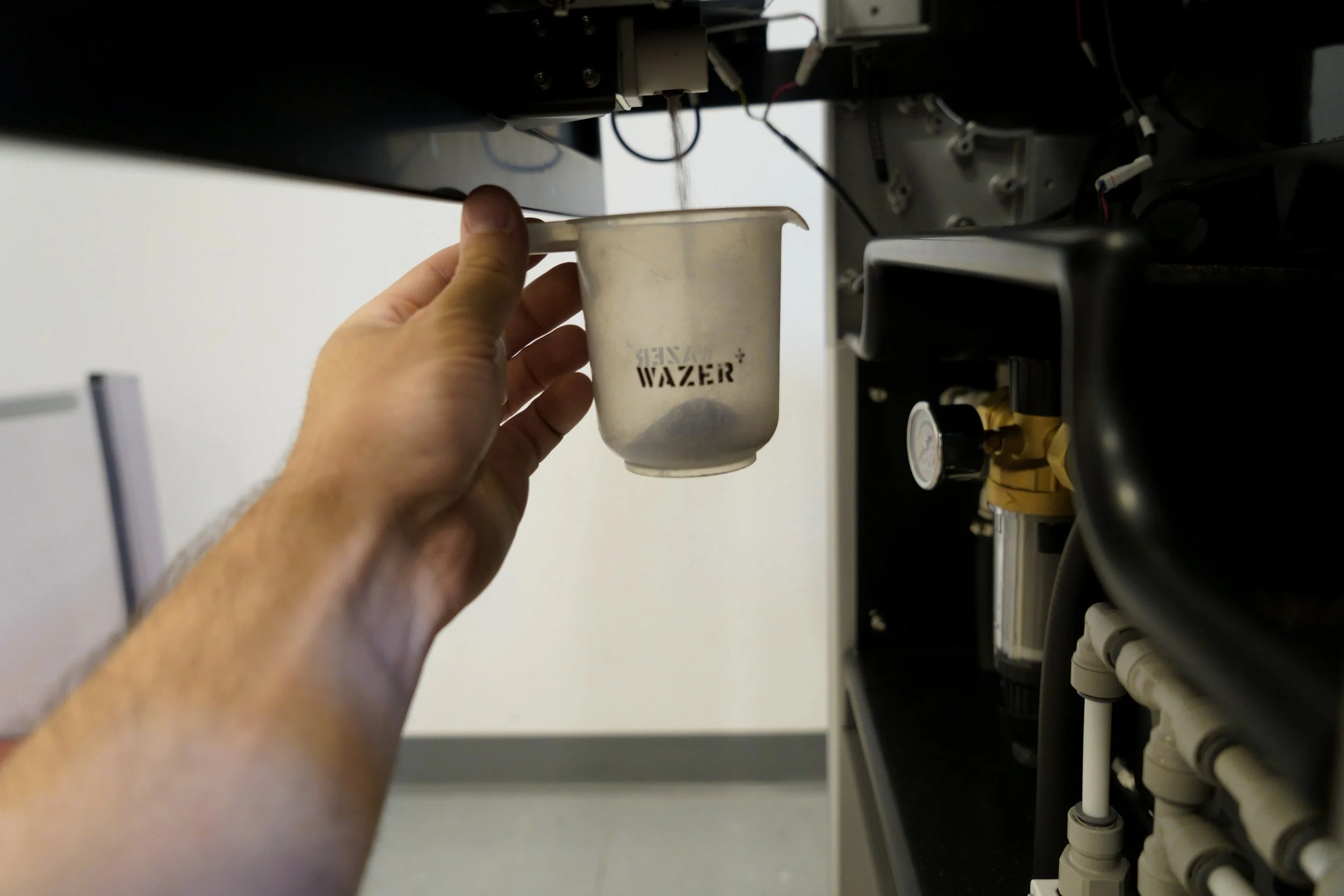
2. With the abrasive hose and abrasive catcher disconnected, conduct an abrasive flow rate check.
3. If the abrasive flow rate is not between 130-150 g/min, conduct a full hopper cleaning by removing the abrasive hopper drain plug and dumping all of the abrasive out of the hopper and into a bucket. Then, open the abrasive pinch valve by pushing the button on the side of the pinch valve and clean the abrasive orifice.
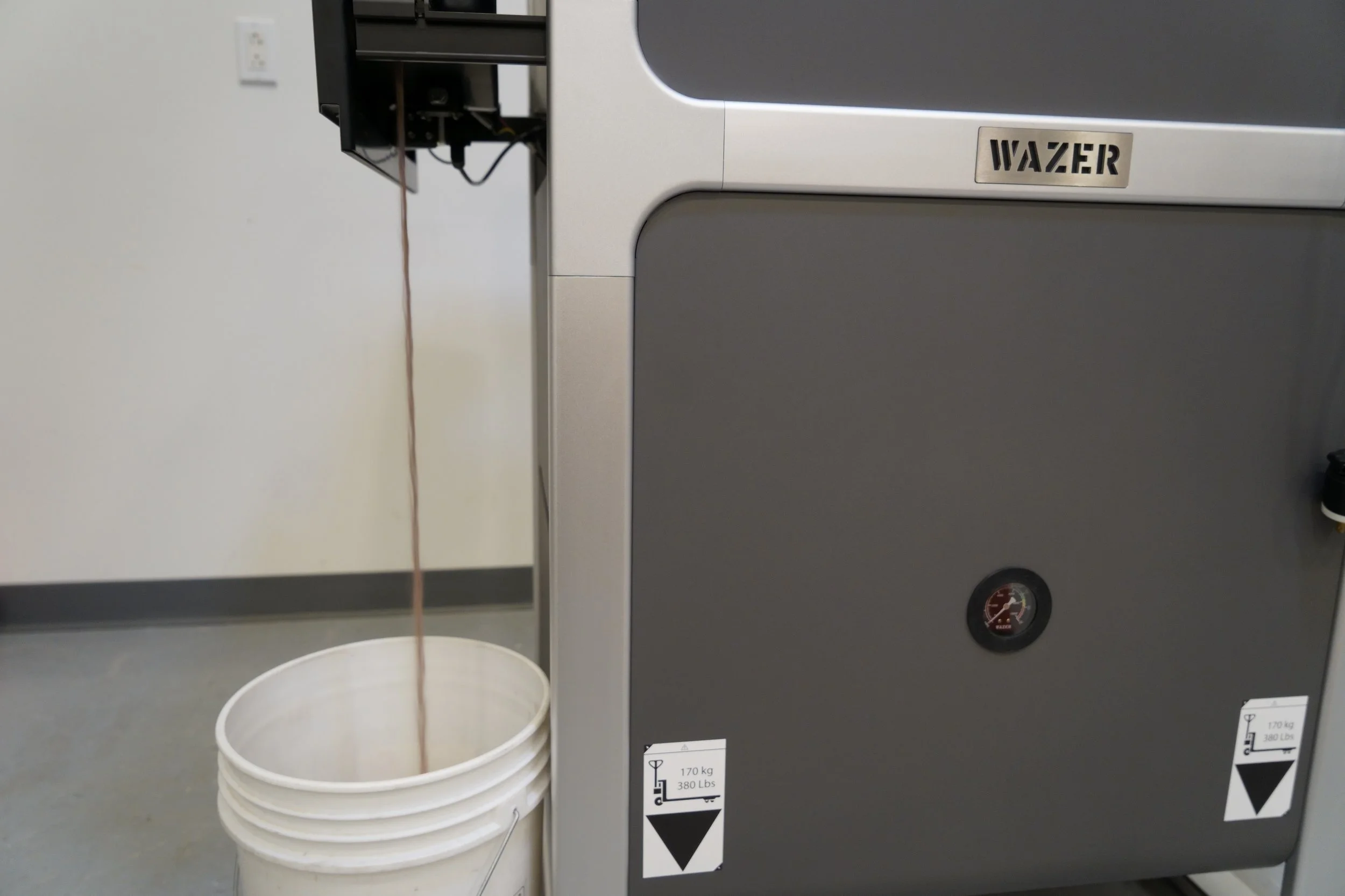
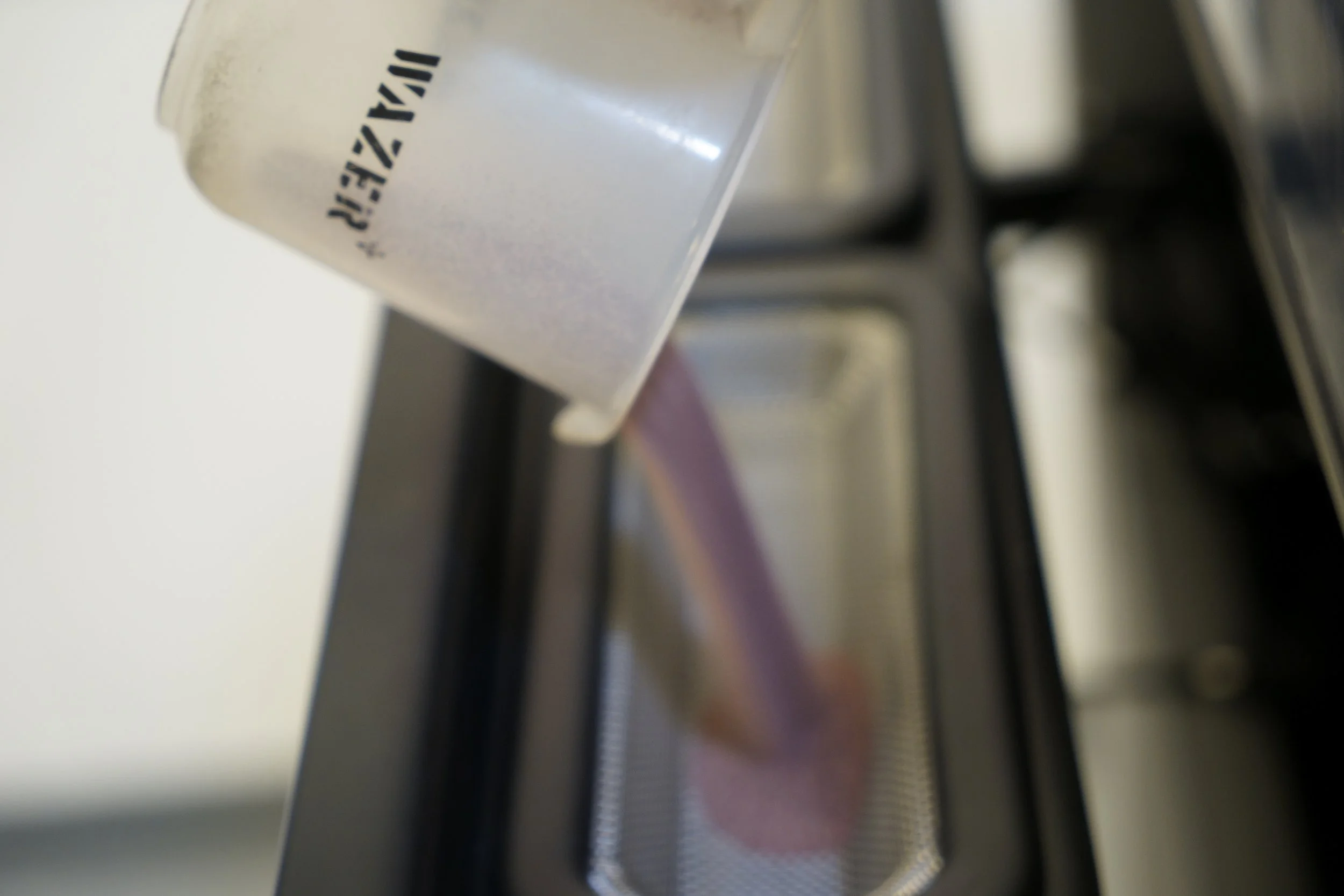
Place a bucket underneath the drain port and remove the drain plug to empty abrasive out of the hopper.

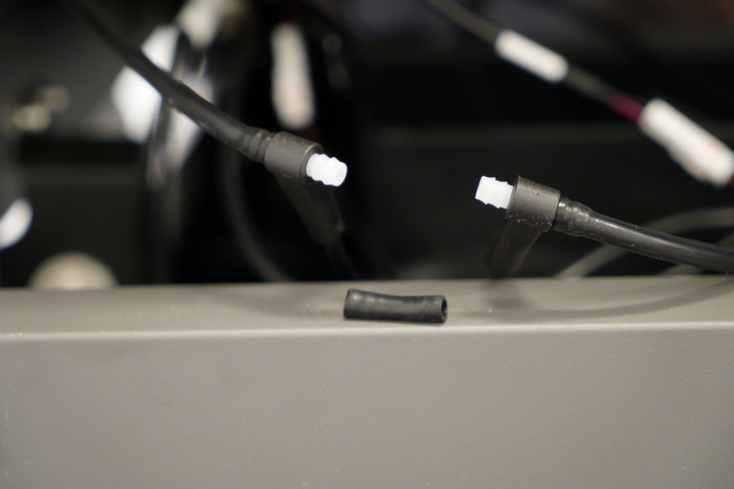
Improper abrasive orifice seating
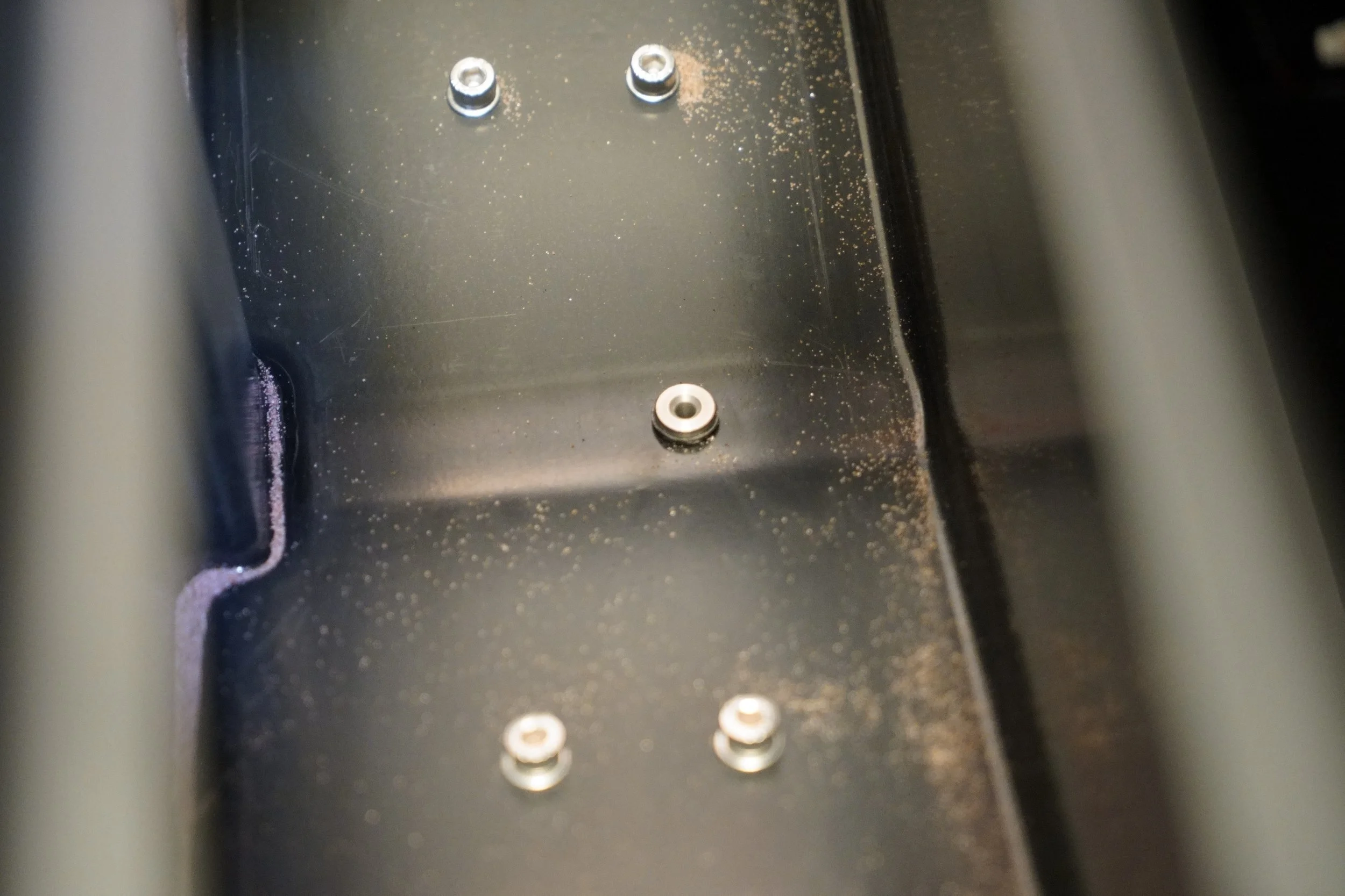
Proper abrasive orifice seating
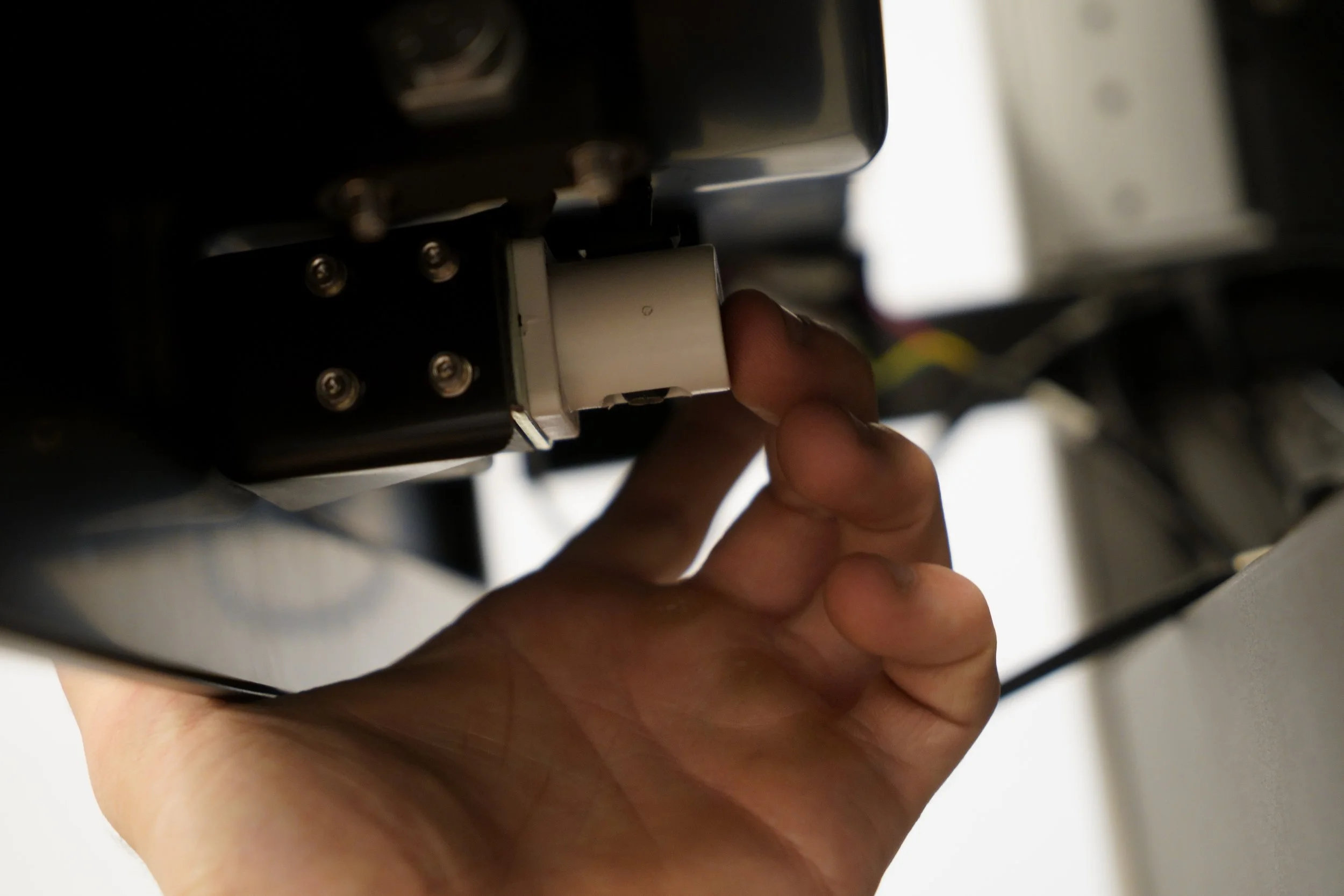
Press the button on the side of the abrasive pinch valve to manually activate it.

While manually activating the pinch valve, blow air through the abrasive orifice to clean the abrasive orifice.
4. Add three cups of unused abrasive to the hopper and conduct another abrasive flow rate check.
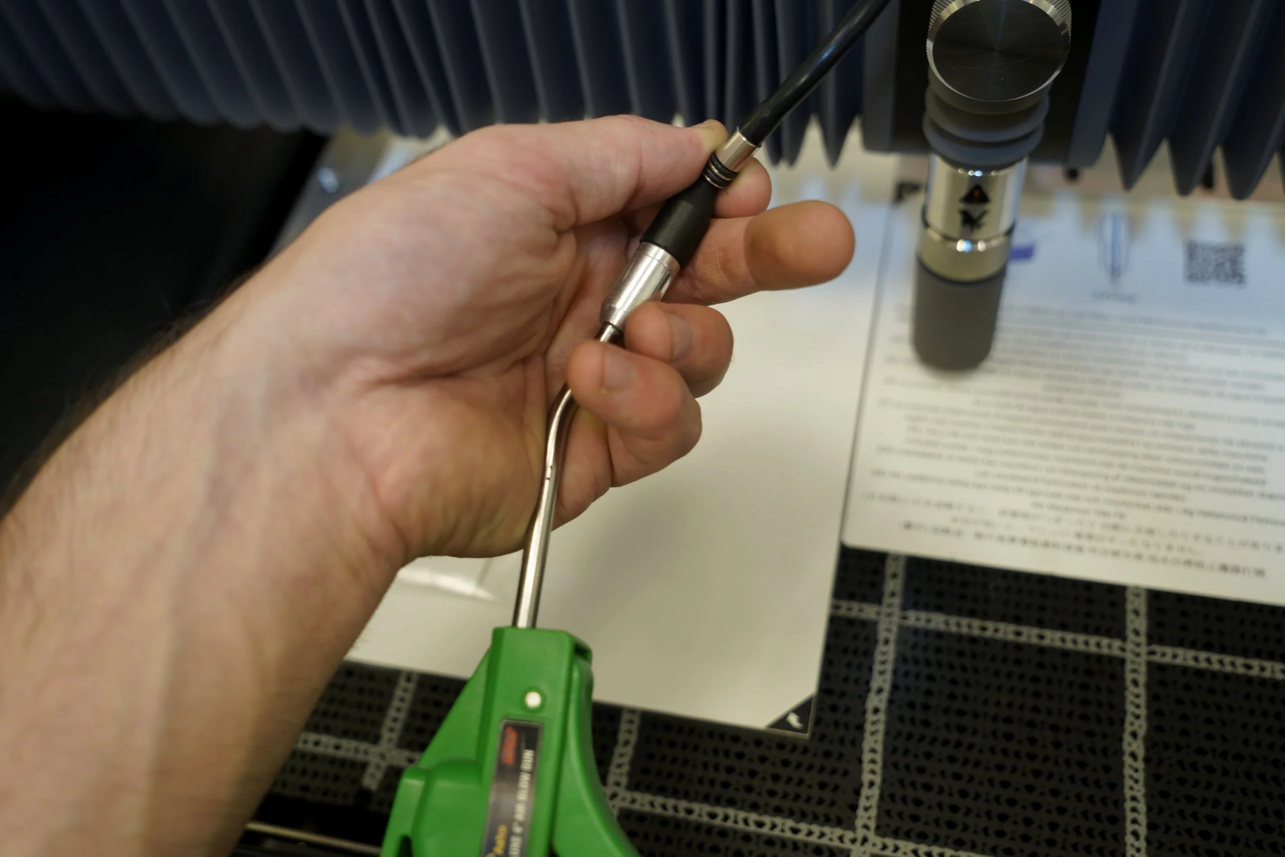
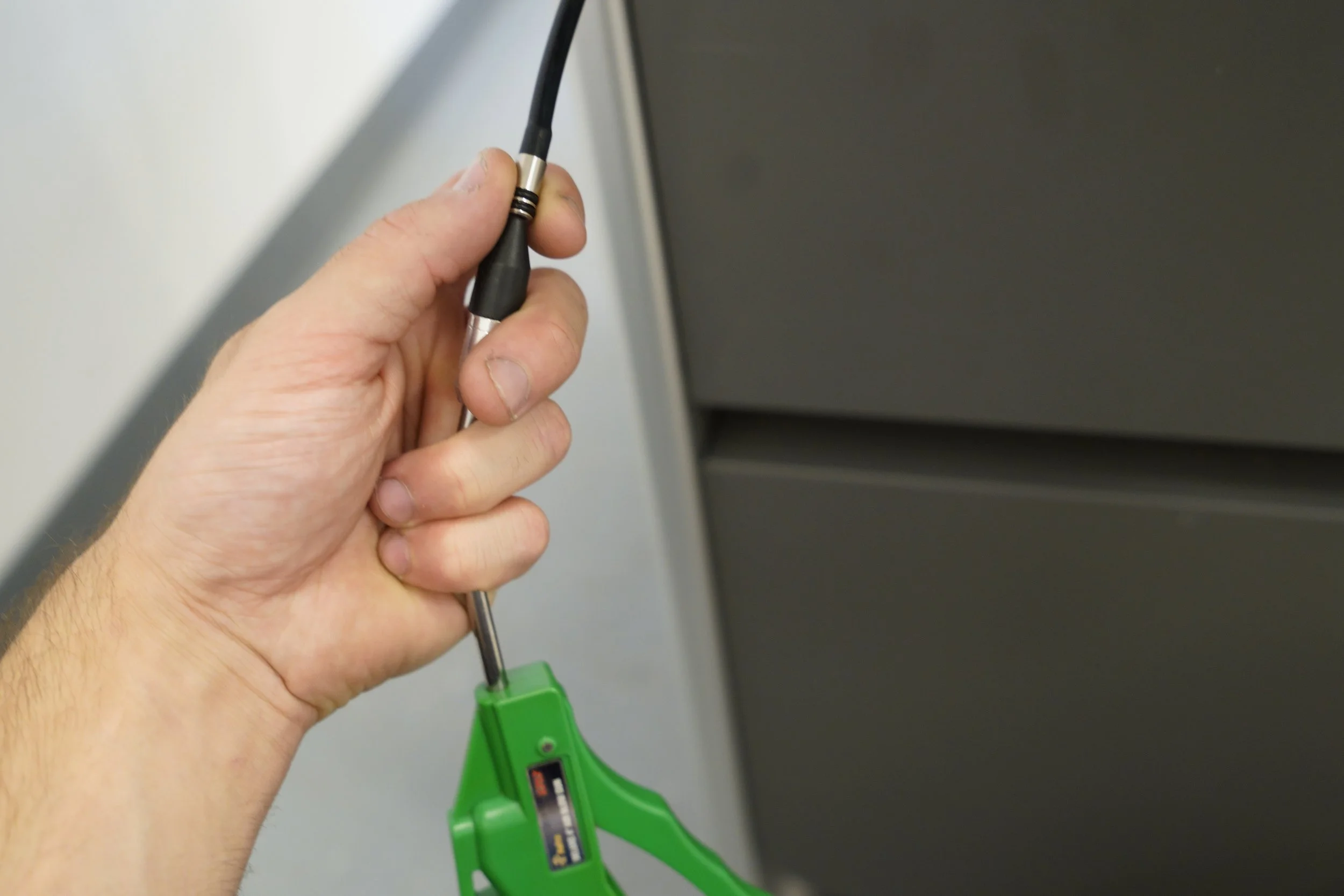
5. Once the abrasive flow rate is between 130 and 150 g/min, conduct a “nozzle purge“ with the abrasive hose disconnected from the hopper and check the pressure and hose suction.
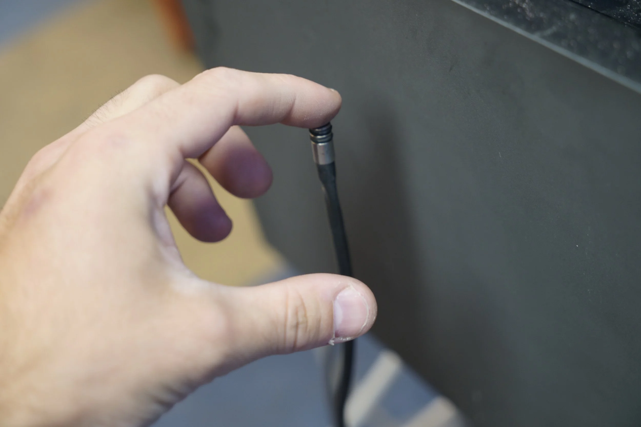
Proper hose suction will ensure that the abrasive hose sticks to your finger during the activation cycles of the nozzle purge.
6. If the abrasive flow rate is sufficient but there is no hose suction, check the abrasive hose line for holes and make sure it is not being pinched in any location.
7. If the abrasive flow rate is sufficient and there is hose suction but still failed cutting, verify the pinch valve and vibration motors functionality.
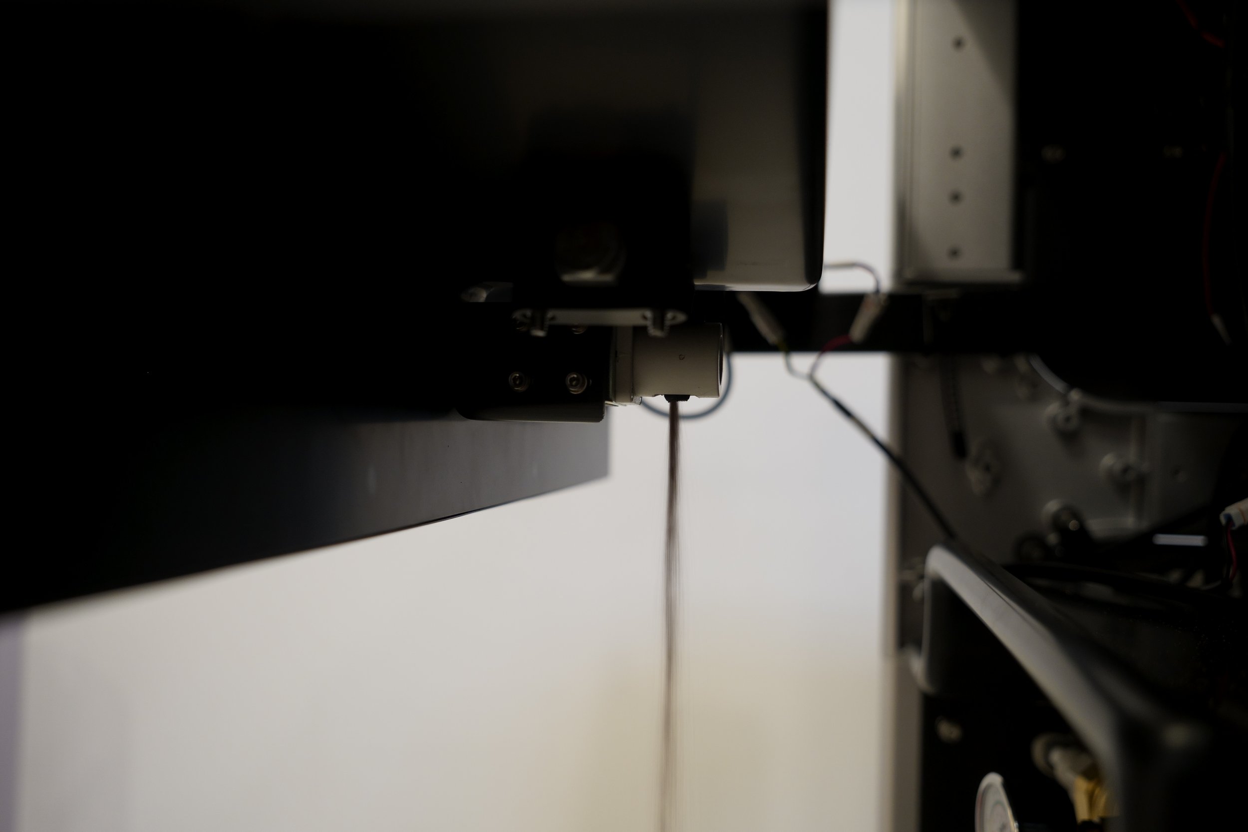
Correct initial pinch valve activation abrasive flow.
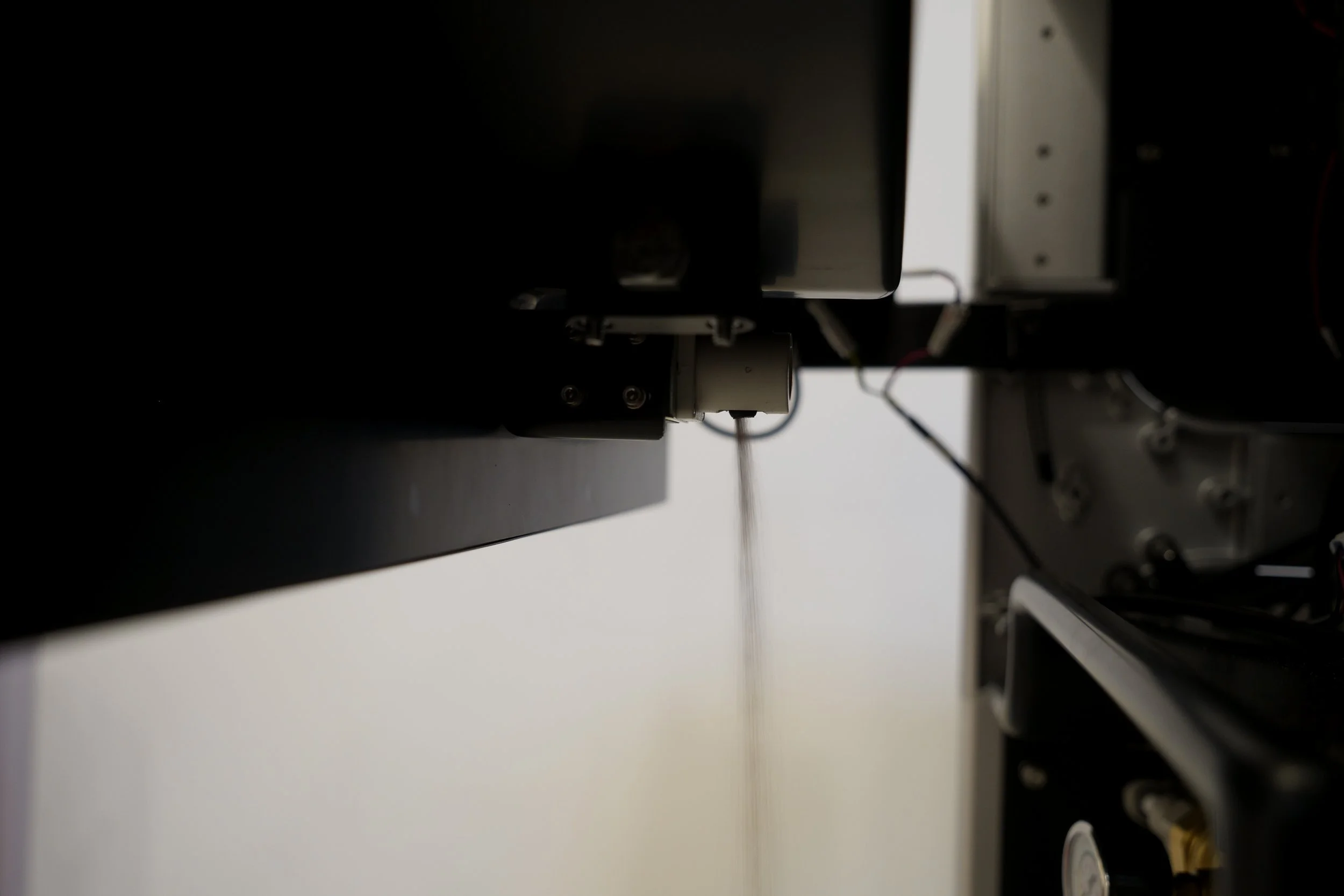
Correct pinch valve sustained open abrasive flow.
Verify vibration motors functionality.
If you encounter a “backflow detected” error message on your machine refer to the steps below:
1. Disconnect the abrasive hose on both ends and blow compressed air through the hose to clear out any potential clogs.
2. Verify abrasive flow through the pinch valve by running an abrasive rate check
3. If the flow is not between 130 - 150 g/min refer to the steps above for cleaning the abrasive hopper and abrasive orifice.
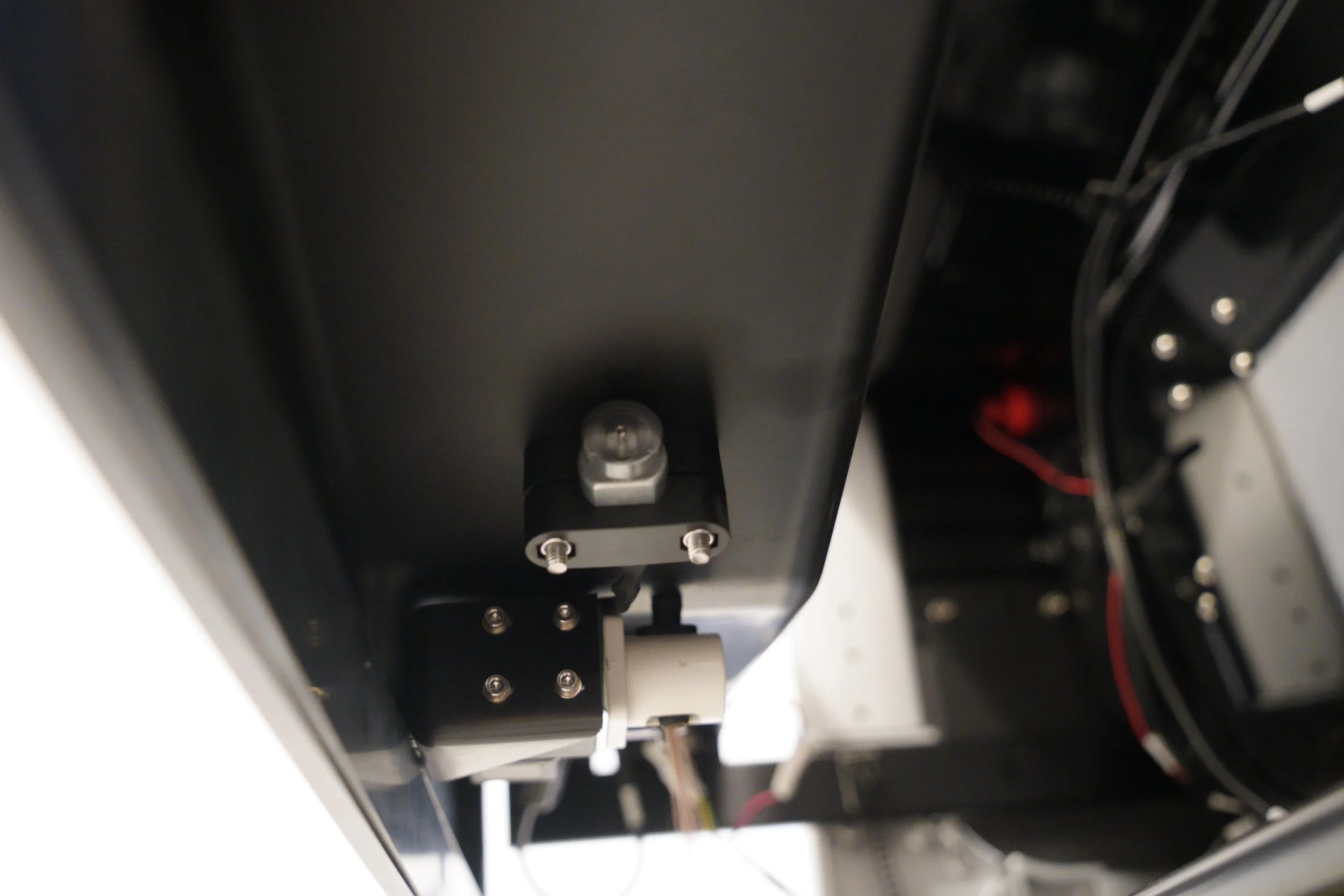
4. If the flow is within the correct range, attempt to resume your cut. If backflow errors persist, emasure the distance between the two backflow sensors at the rear of the machine.
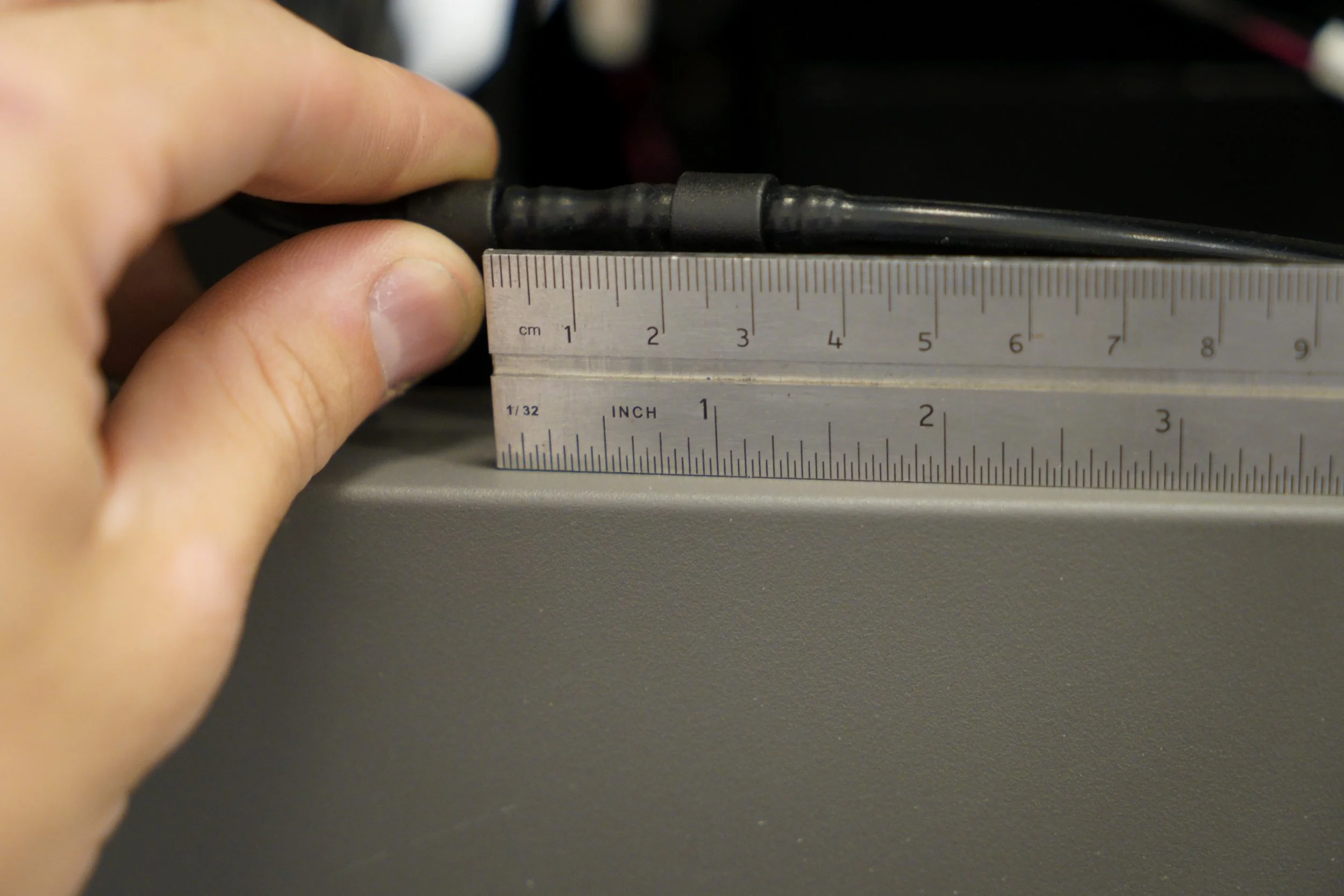
5. If the distance between these two sensors is greater than 25mm, remove the two sensors and cut the hose length to 25mm.
6. Resume cutting. If backflow sensor trips persist, contact customer support.