Mechanical Iris/Aperture
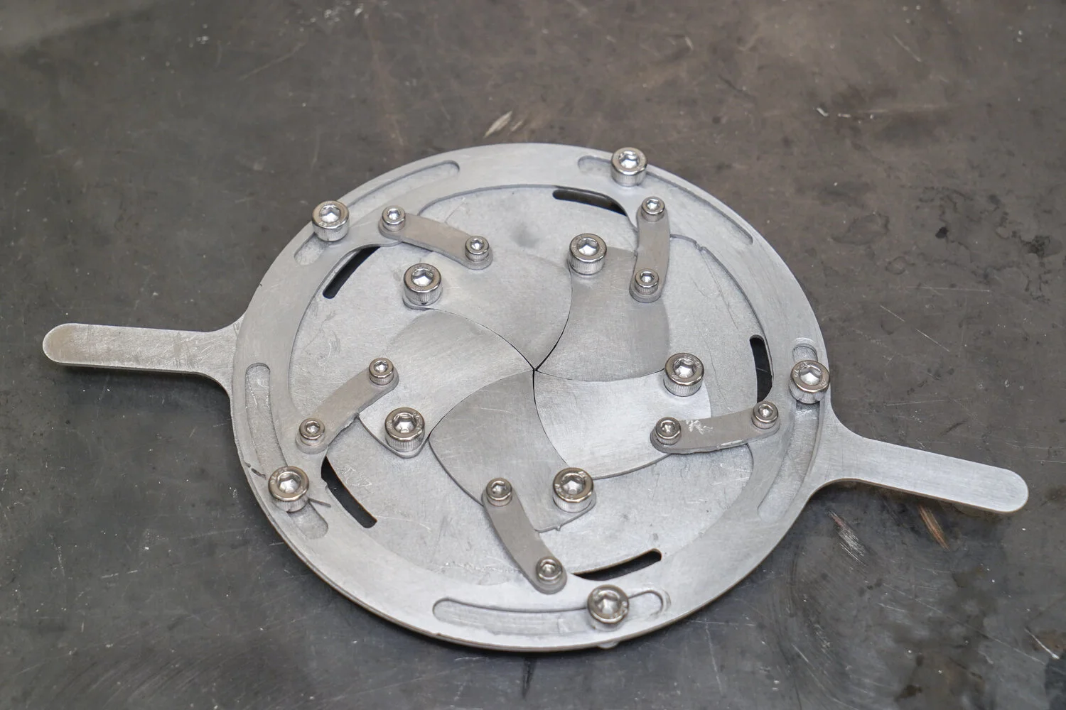
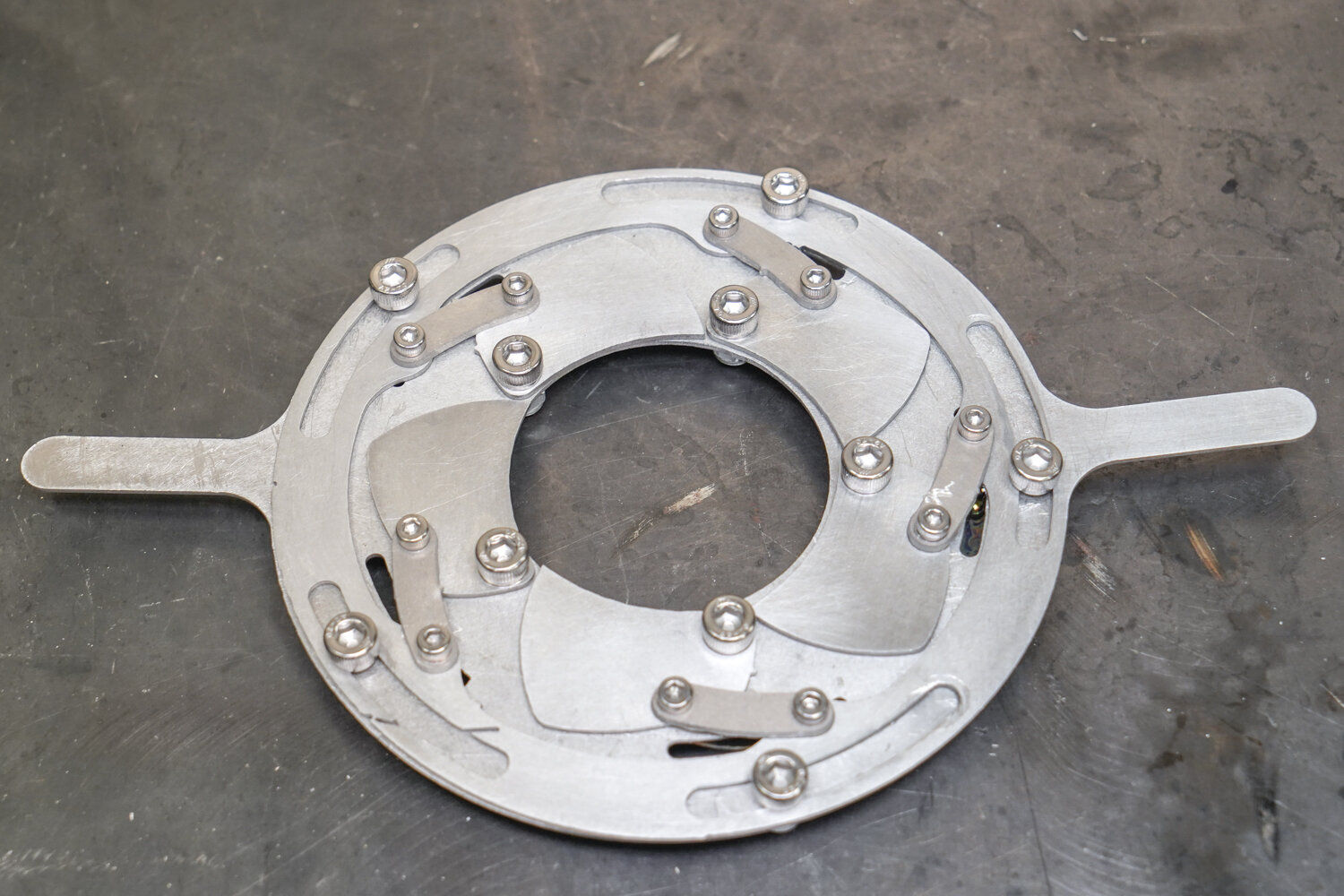


Overview
Sliding surfaces and lubrication are two important files of consideration in any mechanical system . This curriculum is designed to guide you explore the factors that make a sliding surface work, as well as the importance of lubrication by making an mechanical Iris model
Iris, or Aperture is an mechanical structure that is widely used in photography lens and aerospace industry. It has the capability of finely controlling the center opening, and do not post any lateral force when grabbing anything.
Even though WAZER can only cut out 2D design patterns, it does not mean we can only make 2D parts or stationary objects. Through some smart assembly and mechanical design, we can also make objects that moves.
This lesson contains cut files designed for the recommended material, and also customizable design files to create your own cut files. On top of that, a step-by-step guide is also provided. In the end we will have a iris toy that you can appreciate the function of sliding surfaces and importance of lubrication.
Tools needed for these assemblies:
Pliers
Hammer
Deburring Tool
File
Additional Tools needed:
Sandpaper or power sander
4mm and 2.5mm hex wrench
8mm and 6mm sockets or wrenches
Lubricant
Hardware needed:
1.5mm thick Aluminum, at least 150 x 265 mm
10 x M5 Bolts
10 x M5 Locking Nuts
10 x M3 Bolts
10 x M3 Locking Nuts
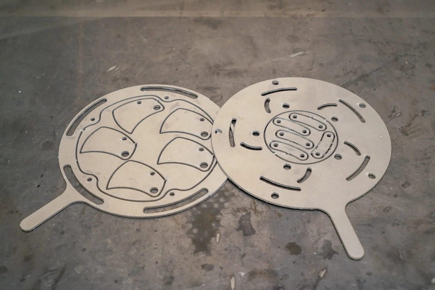
Step 0: Download the Design file from our Downloads page and cut the parts on materials of your choice
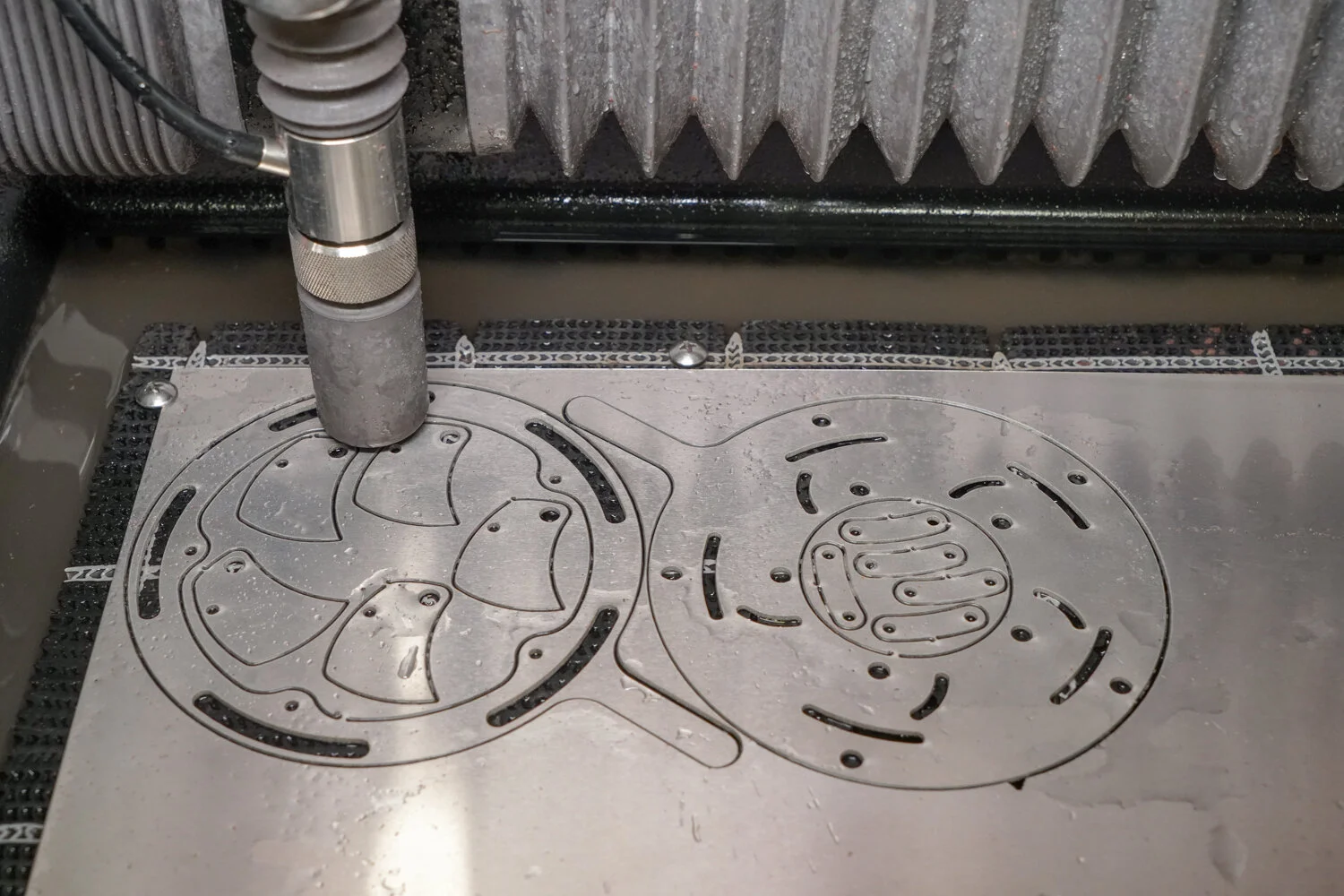
This is what the cut will look like immediately after cutting has finished.
This is a complex assembly with many parts, they are labeled above to aid in the assembly process
Step 1: Deburr All parts
Since there are a multitude of sliding surfaces in this assembly, all parts need to be thoroughly cleaned and deburred so that the assembly moves smoothly. This includes deburring of the holes.
Step 2: Sand/Polish the pieces
After deburring, a light sanding and washing is also recommended to completely ensure smooth sliding.
The more time spent on post-processing, the more smoothly the Iris will operate. Polishing and oiling is unnecessary but will allow the mechanism to operate more smoothly.
[WARNING] Wear gloves when sanding as burrs are very sharp and can cut you.
Step 3: File off Tabs
There are many tabs used when cutting this assembly to keep the pieces in place during cutting. Use a file to remove the tab remnants.
Tab removal is not necessary to the operation of this assembly, but removal provides a better looking end result.
Step 4: Assemble the Backing Plate and Carrier
Use 5 M5 bolts and nylon locking nuts to assemble the backing plate and carrier together.
Put the bolts in the pictured slots in the carrier and align them with the holes in the backing plate. Ensure the handles are opposing each other.
Tighten the nuts with a 4mm hex screwdriver and 8mm wrench enough so that the plates can still slide but will not jiggle up and down.
Step 5: Lube the Carrier and Backing Plate
At this point your assembly should look like this once all 5 bolts have been installed. The carrier and backing plate have a large contact area and lubricant will make the sliding between them easier.
Spray or drip lubricant between the two plates. Slide the pieces to distribute the lube.
If you are having difficulty sliding the two pieces, loosen the bolts. If problems still persist, more post processing (polishing, de-burring, etc.) might be necessary
Step 6: Attach Iris Blades
Attach the blades to the assembly using an M5 Bolt and locking nut
Align the larger hole in the blade with the hole towards the middle in the backing plate.
Tighten the nuts using a 4mm hex screwdriver and 8mm wrench enough so that the blades can still slide but will not jiggle up and down. Repeat for all 5 blades.
Step 7: Attach Arm to Blade
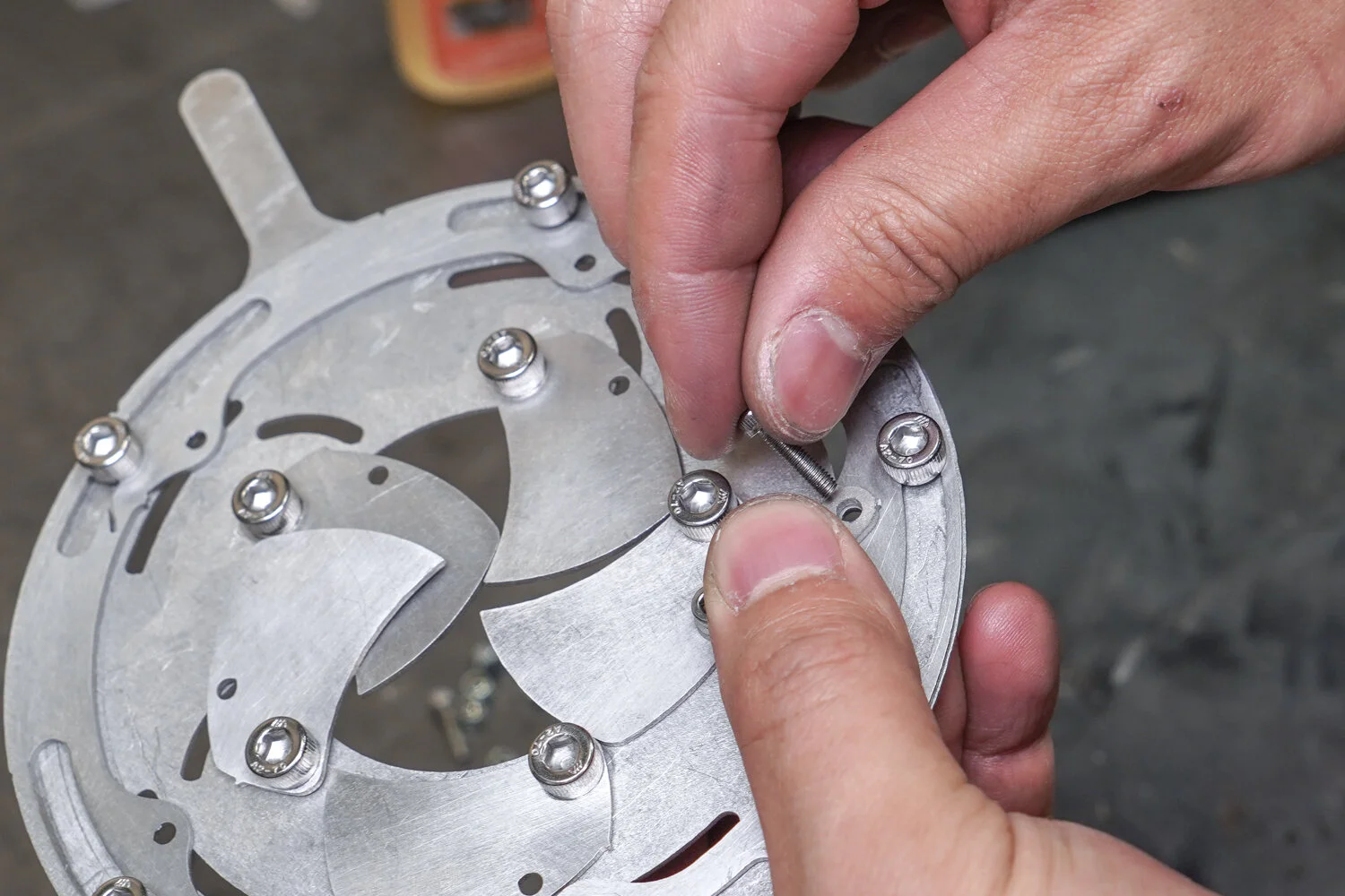
Attach the arms to the blade using an M3 Bolt and locking nut.
Align a hole in the arm with the smaller hole in the blade and the slot in the backing plate.
Insert the M3 bolt and loosely attach the nut to the back of the assembly.
Step 8: Attach Arm to Carrier
Align the other hole in the arm with the pictured hole in the carrier and the aligned slot in the backing plate.
Use a 2.5mm hex screwdriver and 6mm wrench to tighten the nut and bolt. Pliers also work well in place of the wrench. Tighten all the nuts enough so that the arms can still slide but will not jiggle up and down. Repeat steps 7 and 8 for all 5 arms.
The Final Product
Congratulations on completing your Mechanical Iris! Water jet cutting grants you the precision and accuracy needed to make exceedingly complicated mechanisms with multiple moving parts, like this one. The more the assembly is cycled, the easier it will get to move.
