Welcome Cut Multitool
OVERVIEW
WAZER looks like a complex machine to learn and operate. It does not have to be that way. We have designed several welcome cut files for your to have a quick understanding of the machine’s capability.
Among which, the Multitool cut file has a special place. In the process of making this Multitool, you will have the taste of seeing the part emerging from a piece of metal blank, and also get the chance of familiarizing some of the post-processing tools we supplied with the machine.
This lesson contains cut files designed for the recommended material, and also customizable design files for you to make alternation. On top of that, a step-by-step guide is also provided, so you will know what to look out for during the cutting. After that, a quick guide on how to use the hand tools will help you to put on the finishing touches. In the end we will have a multitool that can be very handy in your WAZER operation.
Tools needed for these assemblies:
Pliers
Hammer
Deburring Tool
File
Curriculum Outline
Download the cut files
Cut out the parts
Post Process
Test out the multitool function.
Step 0: Download the Design file from our Downloads page
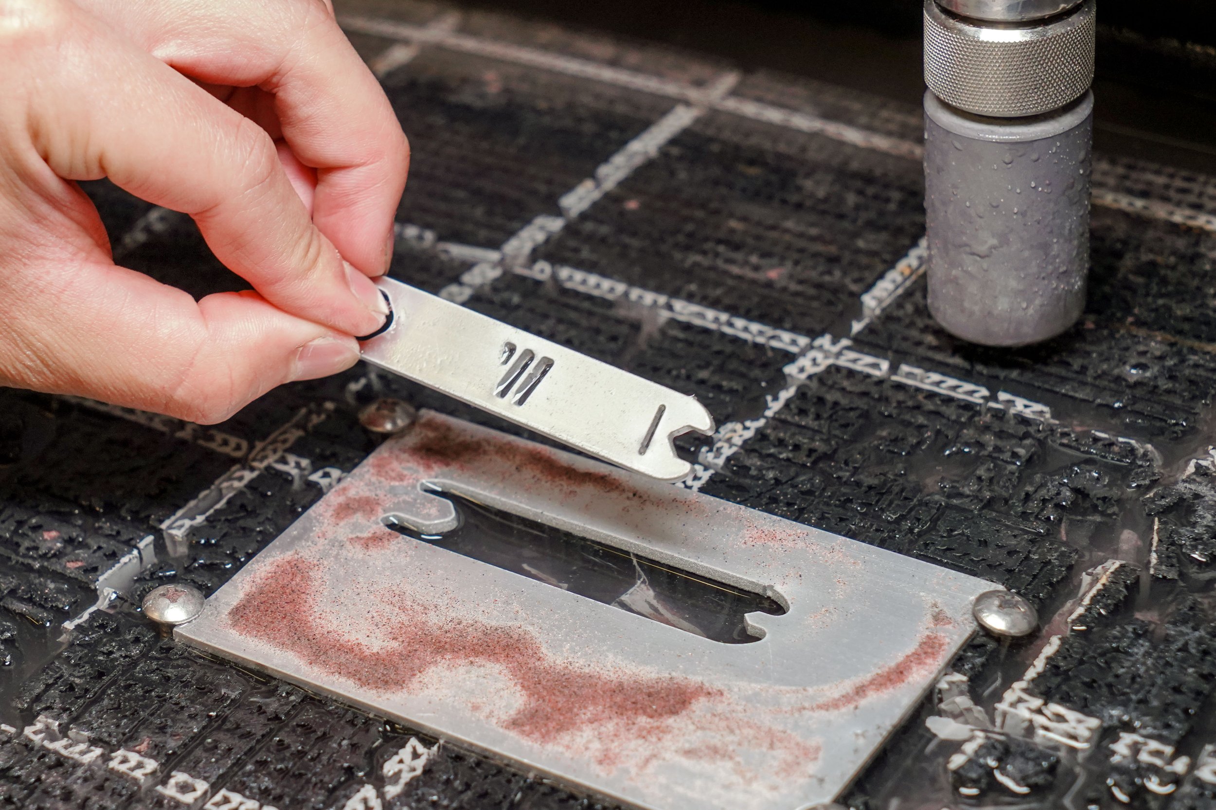
This is what the cut will look like immediately after cutting has finished. But before the cut starts, we need to prepare the machine for operation.
You may download the file from the links above, you can also download a pdf version of this course for offline access.
Cut Preparation
Step 1: Turn on WAZER
Flip the power switch to turn on WAZER. Check the LED is lighting up in the correct sequence. Wait unit you see the middle two LED in the middle column is flickering.
If you WAZER cannot be turned on, please check the water level, and contact WAZER Tech Support immediately.
Step 2: Select Cut File
Load the SD card containing the WAM generated G code into WAZER。
Make sure the cursor points to “Select cut file”, then press OK to go into the SD content page.
Navigate to the selected cut file “Multitool.gcod”
Step 3: Follow the Instruction on the UI Screen
After a g code is selected, the machine will ask you to confirm you want to cut the file.
Then, it will ask you to lift nozzle. By this point, you may freely move the nozzle up and down by hand.
While raising the nozzle assembly, do not put your fingers under the nozzle exit.
Even when the pump box is not turned on at the moment, there is residual pressure in the high pressure hose. In the rare event of high pressure valve malfunction, the residual pressure is enough to cause harm.
Step 4: Machine Homes
After the nozzle is raised up and locked, you may press “OK”.
The machine will energize the gantry motion system, and start sending nozzle to the rear left corner of the machine.
The cutting head will bounce twice on the rear left corner of the machine, and stays there for a while. This entire process is called “homing”, the rear left corner is the “home” position.
WAZER need to home the nozzle assembly every time before a cut.
Step 5: Nozzle Assembly Readies onto Cut Position
After homing, the nozzle assembly will travel to the appropriate location of the cut.
To be precise, it will travel to the “origin” of the cut. Origins of any cut are not the starting point of the first cut, but they are the top left corner of the bounding box of those cut profile.
For more information on “Origin“ and “Bounding box“, please refer to this page
Step 6: Add Abrasive into Abrasive Hopper
After the nozzle travel to the Origin of the cut file, the UI screen will display the relevant information about this cut file. This is a check for the user to make sure the correct cut file is selected.
Then, the WAZER will ask the user to fill in the abrasive hopper, and clean used abrasive bucket.
The used abrasive buckets locate at the front of the machine. Always start cutting with a set of clean buckets as a good habit.
Step 7: Fasten Material to Cut Bed
After the abrasive is filled, and used abrasive bucket is cleared, press OK, and the machine will prompt you to fasten cut material to the cutting bed.
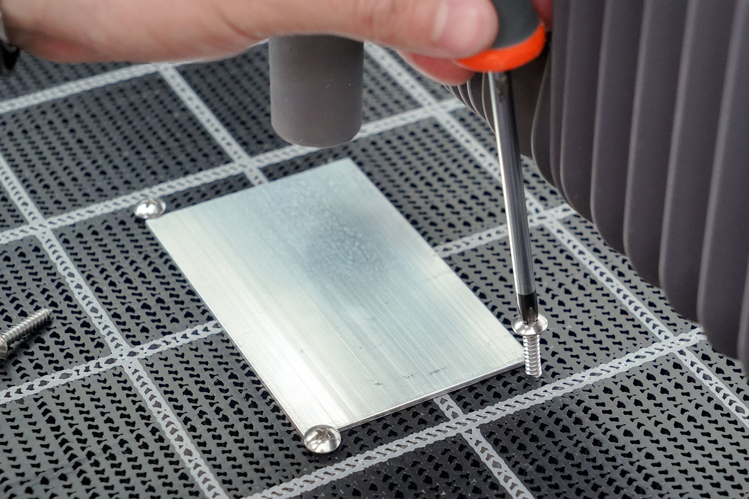
If this is your first cut, you will see a piece of aluminum plate around the center of the cut bed. This is the cut material we are going to use.
If you do not any material on the cutting bed, you may use the provided Philips screws to fasten the material onto the cutting bed.
The idea of fastening material onto cutting bed is to prevent sliding during the cut. Give the material a tug or push after this step to make sure everything is secured.
Step 8: Set Nozzle Height
Nozzle height is a crucial factor that directly affects the machine operation and cut quality. If the nozzle height is too low, high pressure stream will backflow into the abrasive hose and clogs the machine, resulting in partial cut or no cut.
Too high nozzle height will result in less-than-ideal cut quality. Nozzle stream widens after leaving the nozzle tip. Thus cutting with too high nozzle height will result in ticker cut line and degrade edge finish.
You may push the arrow keys to move the nozzle to other places and check the nozzle height there. If the cutting bed is un-levelled, or the cut material is contoured, cut height at different places may be different.
Initiate the Cut
Step 1: Know the Options
Before jumping into the cutting operation, you have the following options to choose from.
Dry Run: Dry run commands the gantry motion system to run through the cut profile under maximum speed, without engaging the high pressure and dry abrasive system.
This helps to ensure the cut does not behave unexpectedly, for example getting stuck in one spot or double cutting
Check Cut Extents:
Cut extents (bounding box of cut) can be checked using the “Check Cut Extents” command. If the cut exceeds material bounds, move the origin or material appropriately.
Move Origin:
The origin (top left corner) of the cut can be moved by selecting the “Move Origin” command and using the arrow keys. Each press shift the nozzle assembly for 10mm.
Restart Cut:
After selecting the “Restart Cut”, gantry system will start tracing the cut profile without engaging the high pressure and abrasive system.
As the nozzle assembly travels near the point where the cut was interrupted, press “Start” button to begin cutting from that point.
Cutting
Step 1: Commit a Cut
Once initialized, press “Cut Material” and then press the “Start/Stop” button to begin cutting.
Step 2: Observe and Check
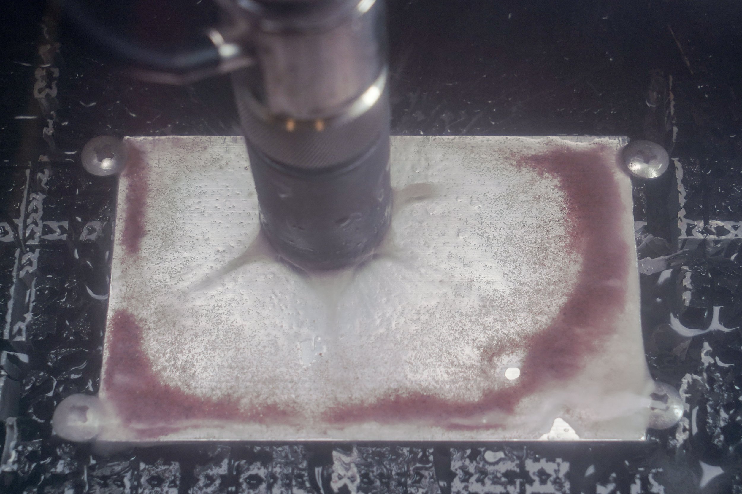
While cutting, ensure the WAZER is functioning properly by checking if abrasive is piling up around the cut point.
High pressure water alone does not cut material, we need the help of abrasive. After abrasive particles impact the cut material, they are pushed outwards and form a circle around the point of cutting. If you see this ring of abrasive, this means the machine is operating as expected.
Another important observation to make is the volume of pierce noise changes from loud to quiet after material is penetrated.
Check for display on pressure gauges.
On the left side of the pump box, you will find a pressure gauge. The needle of the pressure gauge will move when water comes out of the nozzle.
If the needle in your pump gauge is not within the green zone during the operation, this means the pump box is not producing enough pressure. Contact WAZER customer service immediately.
Check for Nozzle movement
If the nozzle is not moving, all it will do is to drill a hole in the cut material.
While cutting aluminum material, you can see the nozzle slowly moving after the initial pierce. Cutting some materials cause the gantry to move faster than others, some tougher materials might cause the gantry to move too slow to observe .
However, if steel or other material are under cut, the nozzle movement may be too slow to tell. In that case, you may check for the changes of X and Y coordinates on the UI screen.
Step 2: Pause if these happen
Before the material if fully pierced, you can expect some water spray. However, if the spray appears like these two pictures, it means the high pressure stream is bouncing off from the cut material surface. That is an indication of failed cutting and an abrasive hose clog.
If this happens, pause the cutting and refer to the user manual for a solution. You may also contact WAZER customer service.
To Pause cutting at any time, press the “Start/Stop” button.
You may press the “Start/Stop” button at anytime to pause the cut. The machine will shut off pump box and abrasive system, but keeps the gantry motion system energized. To resume the cut, press the same button again. Pressing the “OK” button will cancel the cut.
Emergency Shut down
In the case of an emergency, the red emergency stop button can be used to kill the machine. This should only be used in emergency situations.
This big red button is the emergency switch for the whole machine. If you press this button, power to the main unit and pump box will be cut immediately.
Post Processing
Step 1: Cut completion
After the cutting is completed, you will be able to extract the cut piece.
If everything takes place as expected, you will see the the machine complete the cut, and display “cut completed” on the UI screen.
The UI screen also displays the the total time spent on the cutting. Press OK will bring you back to the welcome screen.
After the cut is completed, the gantry motion system is de-energized, and you can manually push the nozzle assembly away from the cut. Then you can pick up the cut piece from the cutting bed.
Step 2: Deburr
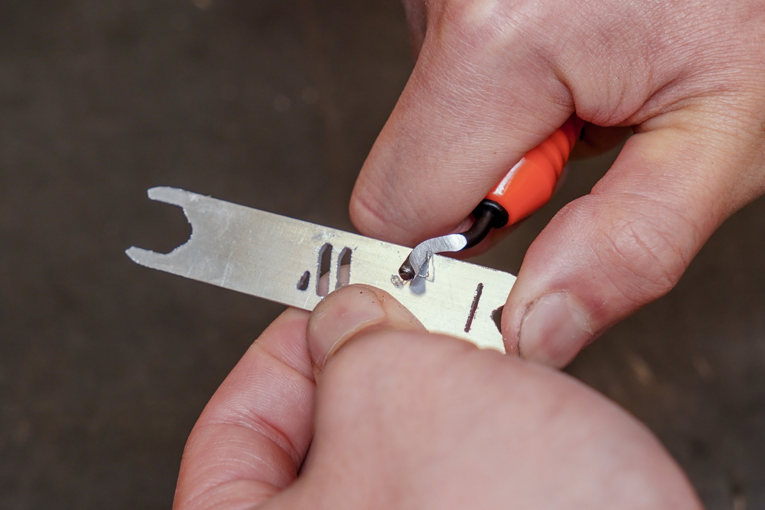
Use the included deburring tool to remove the burrs.
With many materials, sharp burrs are present after cutting on WAZER. There are many methods to deburring including using a deburring tool, sanding, filing or tumbling
The quickest way is to use the included deburring tool
Beware of the sharp burr, put on gloves.
If you have sand paper around you, sanding the freshly cut part is also recommended. It is better to sand the cut piece while it is flat.
Sanding can be used on cuts to improve the edge finish quality and also to improve the aesthetics of certain pieces
The smaller the grit number, the rougher the sandpaper or abrasive. On metals, roughest grit generally used is 150 for removing large amounts of material with ~1000 grit being a finishing grit for metals
Sanding is a huge field with lots of nuance. Type of abrasive used, material being sanded, brand of abrasive, grit and other factors all play an important role in determining what end result will be achieved
For an extra level of literal polish, rubbing and polishing compound can be used to achieve mirror finished on certain surfaces
Step 3: Remove Tab
Tab is the small bridge material that connect the cut piece to the blank. It holds the piece into place until the material is extracted from the machine and the tab is broken off by hand.
Some cuts require tabs to complete. Tabs can be easily broken by bending the part that needs to be removed back and forth until the material cracks using pliers or by hand
Tabs made of a more difficult material to break can be clipped off using wire cutters
If difficulty of breaking tabs off persists, a coping saw or other fine saw can be used to remove the tab, but a smaller tab should be used in the future
The remnants of tabs are very sharp and unsightly but can be cleaned up using sanding or filing
Step 4: File
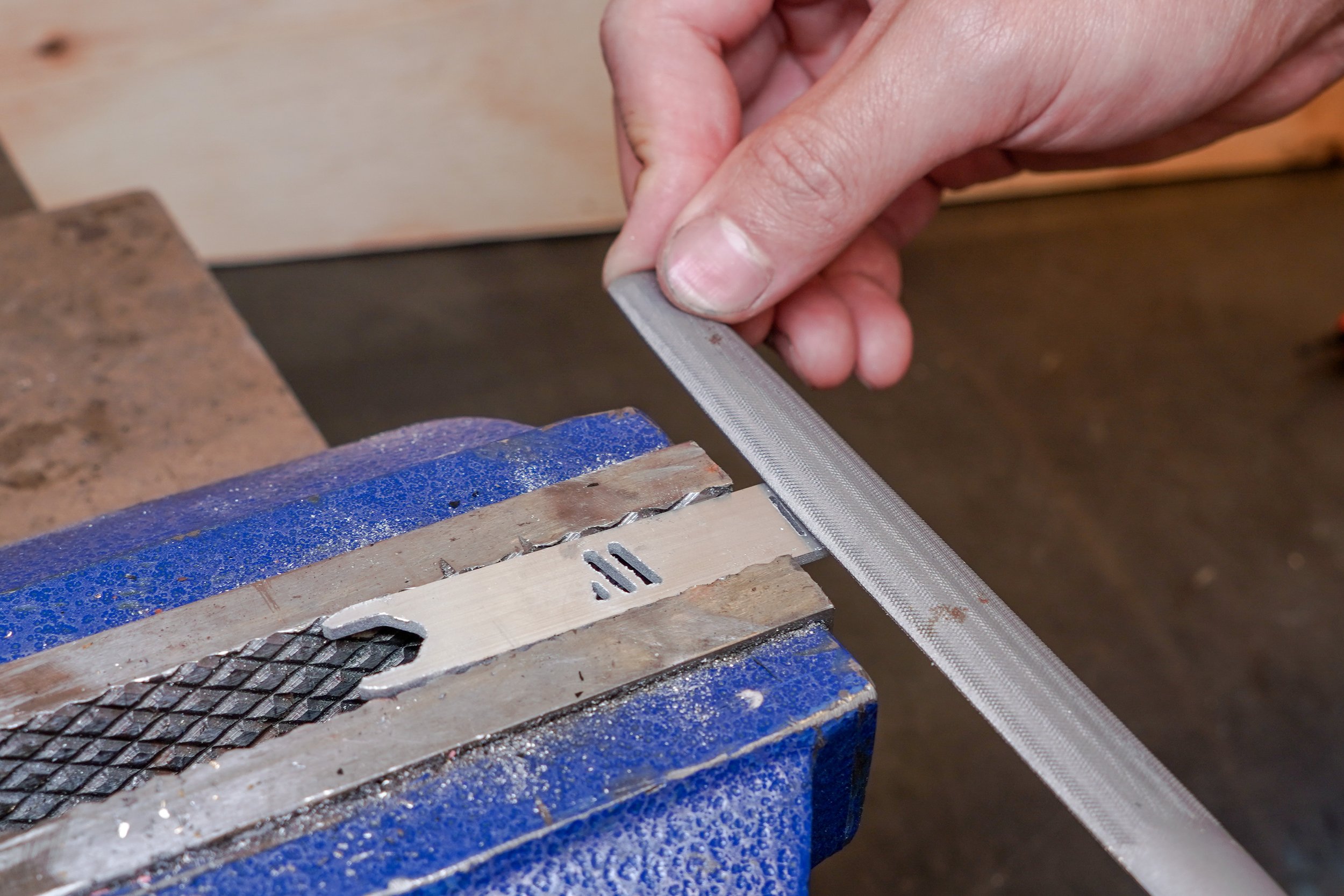
Next, we need to create a slope on the screw extractor prongs, so the prongs can easily slide under the screw flange. We can achieve this by filing.
Filing is used to remove very large amounts of material quickly, like sharp corners or tab remnants. Depending on the material, different files of different granularity should be used to achieve desired finish
Just as with sanding, filing is a nuanced operation with many options and variations
Some materials like Aluminum are extremely soft and easy to file whereas others like stainless steel are very difficult to file
Step 5: Bend
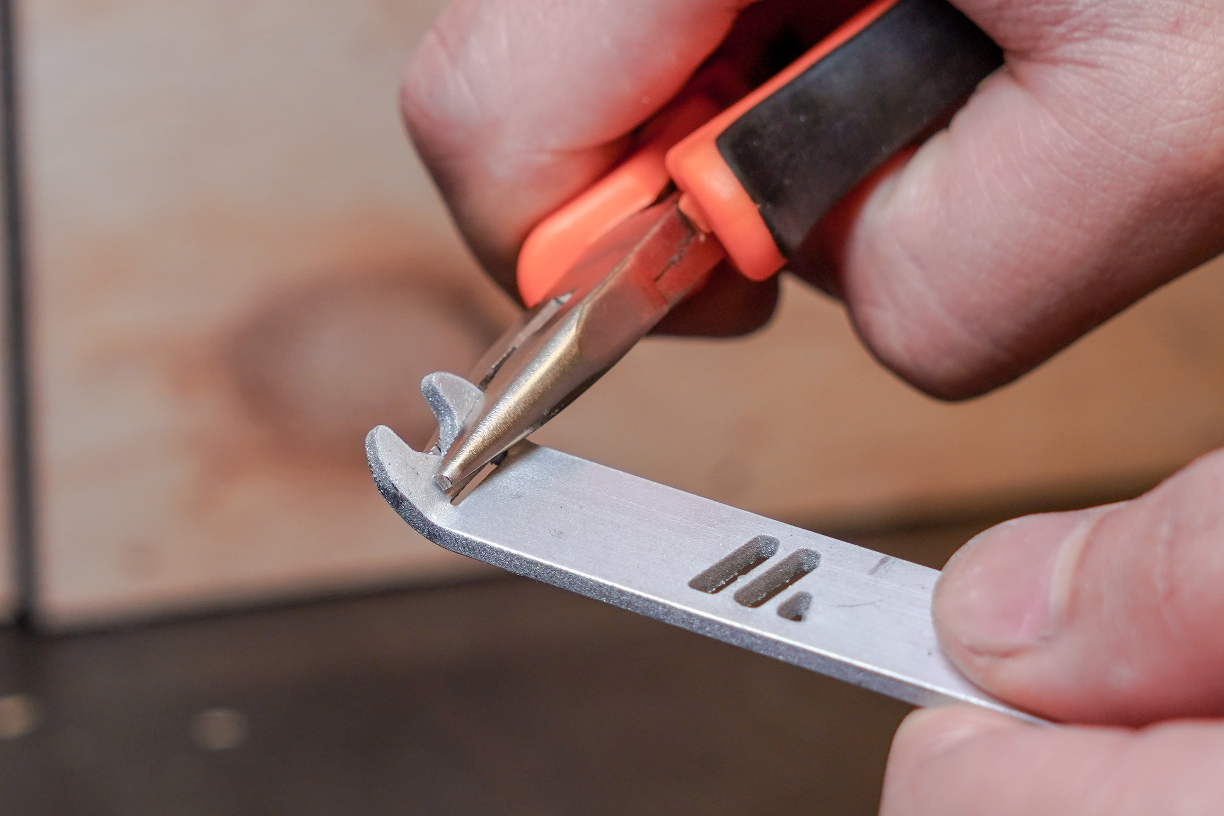
Bent prongs makes the prying motion easier by giving it a pivot point.
Aluminum is soft, so you may simply use the pair of pliers supplied in the tool case to bent the prongs.
When bending many materials, especially on thicker stock, relief cuts or perforations need to be made to ensure a high quality bend. That is why you see a cut out along the bent line.
The End Result
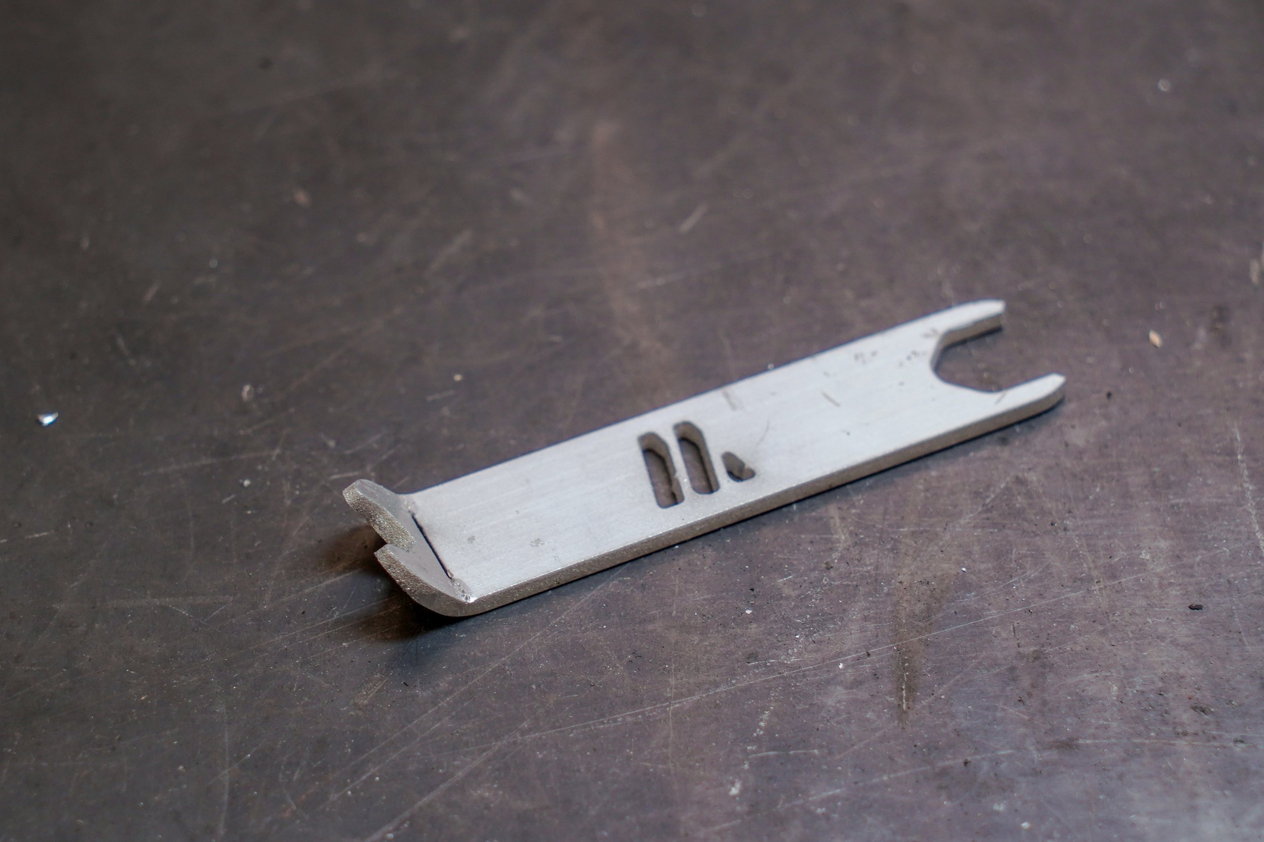
Congratulations, you have successfully made a WAZER Multi-tool !
Here is the end product, a screw extractor and hose puller multi-tool.
This tool has one bent end and one straight end
The bent end can be used to extract stuck screws from the cutting bed
The straight end can assist in unplugging push-to-connect fittings.
The bent end can be used to extract stuck screws from the cutting bed
When the cutting bed wears out, some screws can be hard to come out
You may use the bent end to pry the screw out from the cut bed
The strain end can assist in unplugging push-to-connect fittings.
Push-to-connect fitting has a collar that needs to be pushed in, before the hose can be pulled out.
This tool helps you to push in the collar if you wish to unplug any hoses.


